
|
|
|
|
Week 10:
The assignment is to design and make a board with a sensor, i'm going to use LDR "Light Dependent Resistor" as a sensor.
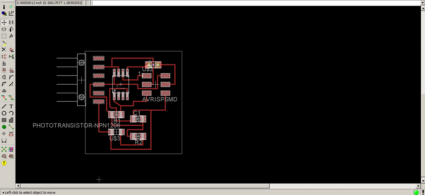
STEP 1: Design the Circuit.
You need (Attiny45, Cap 1uF, 2 Resistors 10K, LDR, ISP Pin Header, 6-Pin Headers) to design your circuit

After finishing the schematic you need to layout the board the step which i consider one of the most difficult steps in electronics production and it needs alot of practice and experience.
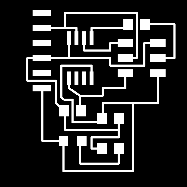
Exported the monochrome, 500 DPI image and opened it in GIMP.Then added about 20 px to width and height and exported the boarder as well.
STEP 2: Mill the circuit.
using Fab modules import the traces image first and choose 1/64 endmill and make the path, send it and mill it !! after that you need to load the boarder png and change the endmill to 1/32 and cut out the boarder to get your board.

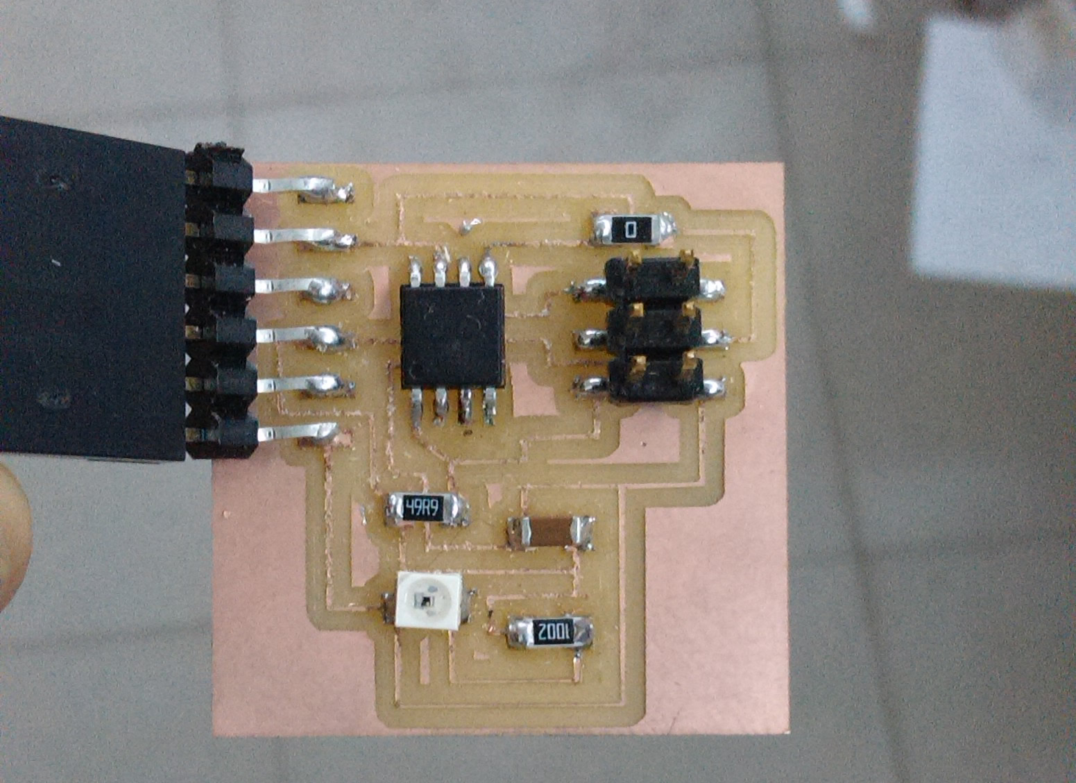
STEP 3: Solder The Circuit
It was a quite easy process, be careful and conenctrate and sting like a Cobra and everything's going to be alright.
STEP 4: Programming
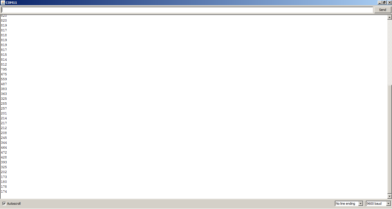
To make sure that everything has gone right i needed to upload a code which write the sensor readings in the serial monitor using Arduino IDE, SoftwareSerial library.
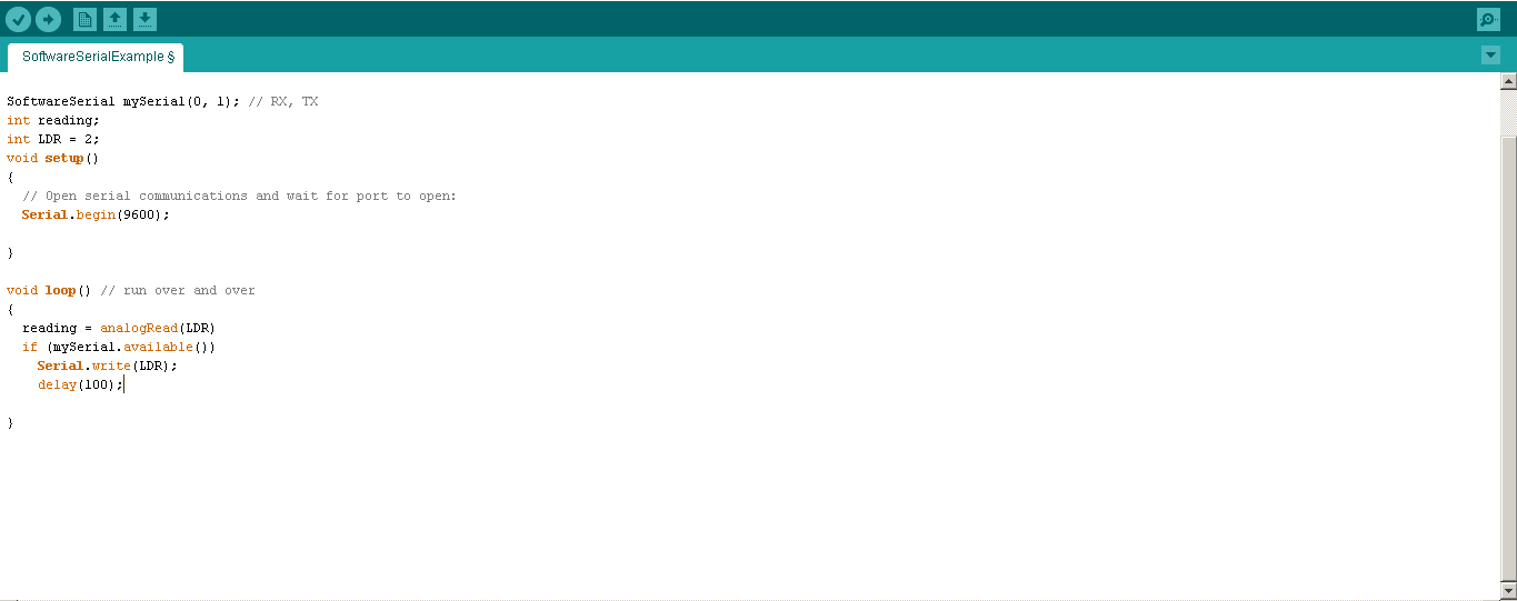
It Worked!! you could see all reading appeared on the serial monitor.
DOWNLOAD FILES |